Rovo Navigation Setup
Important
It is imperative to tune the Rovo according to your requirements before testing it. Be sure to remain vigiliant when the robot is moving autonomously as it can cause severe damage if uncontrolled commands are provided or there is a misconfiguration.
Hardware Requirements
1. Autonomous ground vehicle (AGV)
2. Camera (Visual Odometry)
3. Inertial measurement unit (IMU)
4. Logitech controller
Recommended Hardware
- LiDAR
- Depth Camera
Recommended LiDAR: OUSTER
Recommended Camera: ZED2
Software Requirements
1. Ubuntu 18.04/Ubuntu 20.04
2. ROS-melodic/ROS-noetic
3. MBS Navigation Package
Warning
The provided MBS navigation package allows for point to point navigation utilizing GPS coordinates or indoor map coordinates. It integrates the MoveBase package which in turn allows for collision avoidance. This package is currently designed for 2D planes with a planned expansion for 3D planes. Caution must be exercised when using the package around people and or in an un-constrained environment as any fault in sensors or misconfiguration may lead to an accident.
Configuration
In the provided package, several configuration have to be adjusted which are:
Localization
GPS localization config file
Odom localization config file
MoveBase
Base local planner params
Costmap common params
Global costmap params
Local costmap params
Movebase params
In-depth information is documented by the authors of the robot localization package.
GPS Localization Config
In this configuration file, we combine three sensor readings, which are the robots odom, imu, and the gps.
frequency: 20The frequency depicts the rate at which the node publishes information.
two_d_mode: trueIt tells to ignore the height readings from the incoming sensors as we are navigating in 2D.
publish_tf: truePublishes a transform from the map frame to the odom frame
transform_time_offset: 2Offsets the transform as some packages require transforms to be future off-set by a few seconds.
Setting the sequence of transforms for this localization node.
odom_frame: odombase_link_frame: base_linkworld_frame: mapmap_frame: map
It is important to change the odom to the odom published by your robot.
odom0: /your_robot/odomThis is typically published by the robots controller
odom0_config: [false, false, false, false, false, false, true, false, false, false, false, false,false, false, false]The boolean values are (X, Y, Z, roll, pitch, yaw, Xv, Yv, Zv, rollv, pitchv, yawv, Xa, Ya, Za).
v is velocity and a is acceleration
odom0_differential: trueThis indicates whether the odom velocity should be computed from the given x and y positions.
imu0: /imu/dataimu0_config: [false, false, false, false, false, true, false, false, false, false, false, true, true, false, false]The boolean values are (X, Y, Z, roll, pitch, yaw, Xv, Yv, Zv, rollv, pitchv, yawv, Xa, Ya, Za).
v is velocity and a is acceleration
imu0_differential: falseodom1: /odometry/gpsThis is typically published by the navsat node. Ensure that the correct topic is used according to what you have assigned.
odom1_config: [true, true, false, false, false, false, false, false, false, false, false, false, false, false, false]The boolean values are (X, Y, Z, roll, pitch, yaw, Xv, Yv, Zv, rollv, pitchv, yawv, Xa, Ya, Za).
v is velocity and a is acceleration
odom1_differential: false
It is highly important to tune the process noises.
process_noise_covariance:This determines on how much to trust the incoming data. Each line represents X, Y, Z, roll, pitch, yaw, Xv, Yv, Zv, rollv, pitchv, yawv, Xa, Ya, Za. Values for these are assigned along the diagonals.
initial_estimate_covariance:This determines on how much to trust the initial data. Each line represents X, Y, Z, roll, pitch, yaw, Xv, Yv, Zv, rollv, pitchv, yawv, Xa, Ya, Za. Values for these are assigned along the diagonals.
For more information, the following repository by MethylDragon has a great explanatory guide.
Odom Localization Config
In this configuration file, we combine two sensor readings, which are the robots odom, and imu.
frequency: 20The frequency depicts the rate at which the node publishes information.
two_d_mode: trueIt tells to ignore the height readings from the incoming sensors as we are navigating in 2D.
publish_tf: truePublishes a transform from the odom frame to the map frame
transform_time_offset: 1Offsets the transform as some packages require transforms to be future off-set by a few seconds.
Setting the sequence of transforms for this localization node.
odom_frame: odombase_link_frame: base_linkworld_frame: odom
It is important to change the odom to the odom published by your robot.
odom0: /your_robot/odomThis is typically published by the robots controller
odom0_config: [false, false, false, false, false, false, true, false, false, false, false, false,false, false, false]The boolean values are (X, Y, Z, roll, pitch, yaw, Xv, Yv, Zv, rollv, pitchv, yawv, Xa, Ya, Za).
v is velocity and a is acceleration
odom0_differential: falseThis indicates whether the odom velocity should be computed from the given x and y positions.
imu0: /imu/dataimu0_config: [false, false, false, false, false, true, false, false, false, false, false, true, true, false, false]The boolean values are (X, Y, Z, roll, pitch, yaw, Xv, Yv, Zv, rollv, pitchv, yawv, Xa, Ya, Za).
v is velocity and a is acceleration
imu0_differential: false
MoveBase Local Planner DWA
TEB planner TEB planner tuning
Important
It is important to note that the DWA planner is no longer used and we use the TEB planner. Configuration for the teb planner can be found in the TEB planner wiki. An excellent resource for tuning your TEB planner is vailable in TEB planner tuning.
It is recommended to configure the move base planner to ensure correct movement. Several important ones are:
meter_scoring: trueWhen true distance is measured in meters.
yaw_goal_tolerance: 0.157
Tolerance in radians for movebase.
xy_goal_tolerance: 0.25
Tolerance in xy coordinates for movebase.
path_distance_bias: 0.35
Weighting factor of how close the robot should stay to the path.
goal_distance_bias: 1.0
Weighting factor of how close the robot should attempt to reach the goal.
heading_lookahead: 0.325
Tolerance of looking ahead for available space for turning.
For more information, the following MoveBase Wiki has a brief explanation.
Costmap Common Params
The costmap will be used to integrate and utilize your existing sensor for collision avoidance.Important parameters for this are:
footprint: [[-0.21, -0.165], [-0.21, 0.165], [0.21, 0.165], [0.21, -0.165]]
The footprint defines a square size for the robot. The robots mid point is taken as 0,0 and the the corner points are the distance from the mid point.
footprint_padding: 0.1
Safety-gap that inflates the original footprint.
obstacle_layer:
Sensors that are utilized for sensing. Typically, scan is used for LiDARs and the sort. Important is to change the sensor_frame to match the URDF and the topic to match the input message of the LiDAR.
For more information, the following Costmap Wiki has a brief explanation.
Global Costmap Params
The global costmap of movebase node, as the name states publishes the global costmap. It takes the map, provided by the map server as a static layer. An important point to note is that some warning messages may occur if the on board computer system do not compute the transforms fast enough. These warnings can be ignored.
Local Costmap Params
The local costmap of movebase node publishes the local costmap. It ypically requires the odom frame to operate. However, as we want to depend solely on our GPS, we utilize the map frame for the local costmap as well.
MoveBase Params
The movebase params are important for changing the planner frequency and controller frequency. Usually the default settings are sufficient.
recovery_behavior_enabled: false
It rotates the robot to recover from faulty planning failures or positioning, at times this is not desirable and may need to be turned off.
Simulation Navigation
The first step is to begin the simulation and the navigation stack via:
roslaunch rovo_gazebo gazebo_world.launch
roslaunch rovo_navigation odom_navigation.launch
The second step is to ensure that both the MBS ROVO2 are in the same location on the map and in Gazebo. If the position is different, then on the
Toolbar of rviz, select the2D pose estimateand correct the position so that it closely matches the position in the simulator, the ‘Adaptive Monte Carlo Localization (AMCL) should correct the position of the robot as it moves around on the map.Next, select the
2D Nav Goal; then select a position in the map within the white space, click and drag towards the direction in which you want to robot to move to.
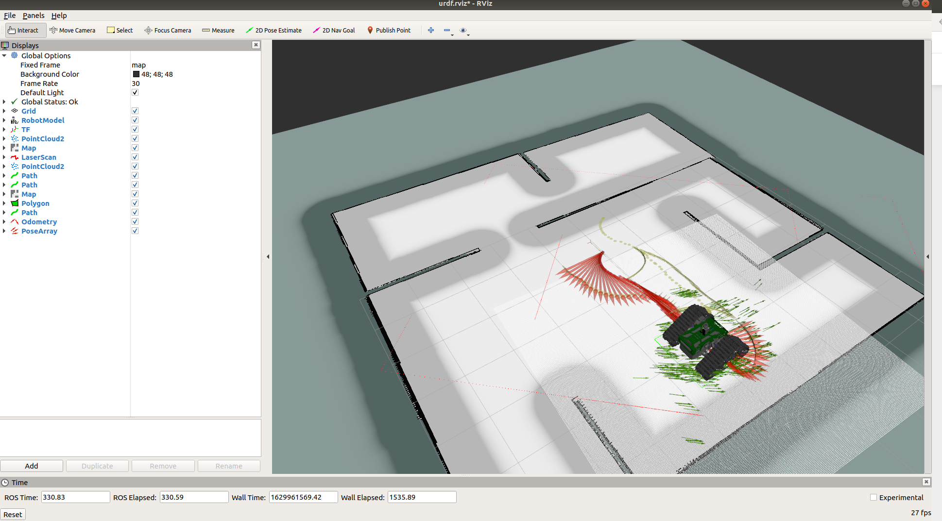
The robot should begin path planning and move both in the simulator and in rviz. The movement may not match if the simulator is not powerful enough.
Rovo Mapping
Simulation Mapping
A sensor device is required with the Rovo for mapping such as a depth camera or a lidar.
For autonomous navigation, the first step is to build a map of the environment. The map can be built either for a virtual environment or the real environment. For mapping, the first step is to load up the simulation and the pre-configured Rviz file.
roslaunch rovo_gazebo gazebo_world.launchThe next step is to open a new terminal and start the gmapping tool via:
roslaunch rovo_navigation map_navigation.launchThe next step is to begin mapping, this is done by either moving the robot using the remote control or via teleop:
rosrun key_teleop key_teleop.py key_vel:=rovo_velocity_controller/cmd_velOnce the entire region is mapped, you can save the map via the following command:
rosrun map_server map_saver -f rovo_mapYou will get two files in the directory from which you run the
map_savercommand; first isrovo_map.pgmand second isrovo_map.yaml. Place these maps inside ofrovo_navigation/maps.Next navigate towards
rovo_navigation/launch/rovo_navigation_stack.launchand replace the room_map.yaml with the updated map, in this caserovo_map.

Real-world Mapping
Steps 2-6 for setting up the map environment for the real-environment is identical. Only in step 1, you must run this command instead of the previous one:
rosrun gmapping slam_gmapping scan:=base_scan
Rovo Localization
Once the mapping is set up, the ROS navigation stack can be verified. For this, first, run:
roslaunch rovo_gazebo gazebo_world.launchNext run:
roslaunch rovo_navigation map_navigation.launch
At this point, the rovo, particle cloud, map should be visible, meaning that the navigation stack is working, for controlling the robot, you can view it in the
Rovo Controlssection.